- 您现在的位置:买卖IC网 > Sheet目录372 > 101-1293 (Rabbit Semiconductor)RCM4510W DEV KIT
�� �
�
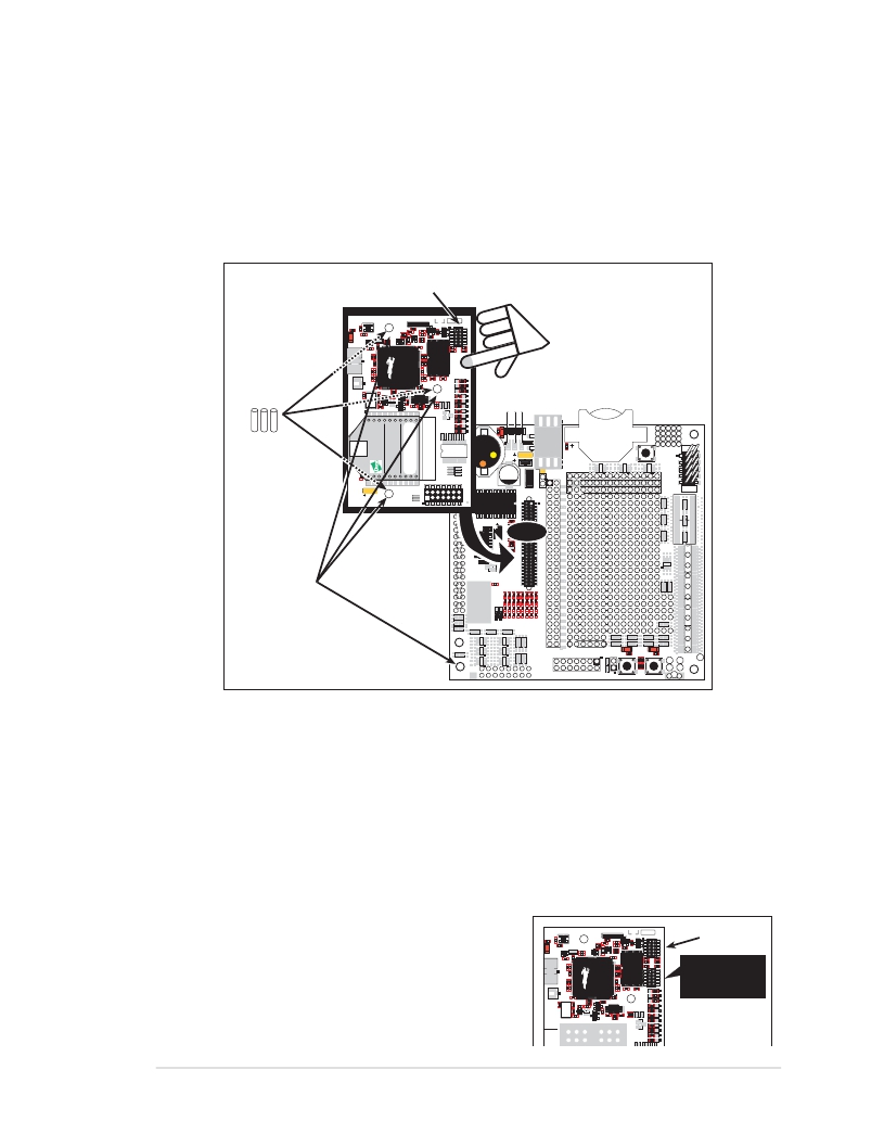
�2.2.2� Step� 2� —� Attach� Module� to� Prototyping� Board�
�Turn� the� RCM4510W� module� so� that� the� mounting� holes� line� up� with� the� corresponding�
�holes� on� the� Prototyping� Board� with� the� programming� header� at� the� top� right.� Insert� the�
�metal� standoffs� as� shown� in� Figure� 4,� secure� them� from� the� bottom� using� the� 4-40� screws�
�and� washers,� then� insert� the� module’s� header� J1� on� the� bottom� side� into� socket� RCM1� on�
�the� Prototyping� Board.�
�Programming�
�Header�
�RCM4510W�
�R3�
�C40�
�C9�
�C8�
�C46�
�C41�
�R19� U11�
�R20�
�R14�
�C27�
�C16�
�C4�
�JP1�
�C23� C1�
�C20�
�U1� C21�
�C42� C22�
�Q8�
�C5�
�U17�
�C35�
�C34�
�JP2�
�JP3�
�JP4�
�JP5�
�C44�
�C82�
�R65�
�C84�
�R61�
�JP6�
�JP7�
�JP9�
�JP8�
�C1�
�U1�
�1�
�Insert� standoffs�
�between�
�mounting� holes� and�
�Prototyping� Board.�
�R52�
�R33�
�R31�
�R30�
�R35�
�R32�
�C5�
�L1�
�C6�
�C2�
�RCM1�
�/RST_OUT�
�/IOWR�
�J2�
�GND�
�/I� ORD�
�/� RST_IN�
�+5� V�
�GND�
�+3.3� V�
�UX47�
�BT1�
�UX49�
�UX4�
�S1�
�RESET�
�RX81�
�R51�
�VBAT�
�EXT�
�PA1�
�PA0�
�PA2�
�RCM1�
�U3�
�C18�
�JP16�
�JP6�
�JP5�
�JP12�
�JP4�
�JP3�
�JP14�
�JP8�
�C16� JP7�
�JP18�
�JP9�
�JP10�
�PA3�
�PA5�
�PA7�
�PB1�
�PB3�
�PB5�
�PA4�
�PA6�
�PB0�
�PB2�
�PB4�
�PB6�
�RX83�
�RX11�
�UX30�
�C15�
�R25�
�PB7�
�PC1�
�PC0�
�PC2�
�Q1�
�PC3�
�PC5�
�PC4�
�PC6�
�UX10�
�R29�
�PC7�
�PE1�
�PE0�
�PE2�
�RX67�
�UX12�
�Line� up� mounting�
�holes� with� holes�
�on� Prototyping� Board.�
�RX43�
�RX97�
�RX49�
�RX55�
�R20�
�R10�
�RX57�
�RX59�
�PE3�
�R19�
�PE5�
�R9�
�PE7�
�PD1�
�LN1�
�PD3�
�LN3�
�PD5�
�LN5�
�PD7�
�LN7�
�PE4�
�PE6�
�PD0�
�LN0�
�PD2�
�LN2�
�PD4�
�LN4�
�PD6�
�LN6�
�CVT�
�RX75�
�RX73�
�CX27�
�UX14�
�DS3�
�R22�
�VREF�
�AGND�
�CX25�
�DS2�
�JP25�
�R23�
�CX23� RX77�
�R21�
�R24�
�RX79�
�UX16�
�UX3�
�J3�
�1�
�1�
�GND�
�S2�
�S3�
�GND�
�GND�
�Figure� 4.� Install� the� Module� on� the� Prototyping� Board�
�NOTE:� It� is� important� that� you� line� up� the� pins� on� header� J1� of� the� module� exactly� with�
�socket� RCM1� on� the� Prototyping� Board.� The� header� pins� may� become� bent� or� damaged�
�if� the� pin� alignment� is� offset,� and� the� module� will� not� work.� Permanent� electrical�
�damage� to� the� module� may� also� result� if� a� misaligned� module� is� powered� up.�
�Press� the� module’s� pins� gently� into� the� Prototyping� Board� socket—press� down� in� the� area�
�above� the� header� pins.� For� additional� integrity,� you� may� secure� the� RCM4510W� to� the�
�standoffs� from� the� top� using� the� remaining� three� 4-40� screws� and� washers.�
�C8�
�R14�
�C23� C1�
�NOTE:� If� you� are� using� the� preview� version� of�
�the� RCM4510W,� do� not� connect� the� program-�
�ming� cable� to� header� J3� (shown� below� the�
�programming� header� at� right).� Header� J3� is�
�used� only� by� the� factory.�
�R3�
�C40�
�C9�
�C16�
�C20�
�U1� C21�
�C42� C22�
�Q8�
�C46�
�C41�
�R19� U11�
�R20�
�C4�
�C5�
�U17�
�C35�
�C34�
�C27�
�JP2�
�JP3�
�JP4�
�JP1�
�Programming�
�Header�
�Do� not� use�
�header� J3� for�
�programming�
�JP5�
�C44�
�C82�
�R65�
�C84�
�R61�
�JP6�
�JP7�
�JP9�
�JP8�
�User� ’s� Manual�
�11�
�发布紧急采购,3分钟左右您将得到回复。
相关PDF资料
101-8430-09-203
LED BASE SUBMINI PANEL INDICATOR
103-0537-403
CAP PMI OILTIGHT 1" CLEAR
103-1234-403
CAP LG PANEL IND BLUE OIL TIGHT
103-1336-403
CAP PMI TORPEDO 1" LIGHT YELLOW
103-3101-05-103
LED BASE T-3 1/4 PANEL OIL TIGHT
1032DX5
INDICATOR NEON GREEN PANEL MNT
1033QD5
NEON IND GRN LITE PANEL MNT QC
1034
LAMP INCAND S-8 DBL INDEX VOLT
相关代理商/技术参数
101-1294
功能描述:处理器配件 12VDC POWER SUPPLY REPLACES 101-0686 RoHS:否 制造商:Olimex Ltd. 产品:Cable 用于:
101-1295
功能描述:处理器配件 RCM5600W Antenna Kit
RoHS:否 制造商:Olimex Ltd. 产品:Cable 用于:
10-112989-1
制造商: 功能描述: 制造商:undefined 功能描述:
10112A WAF
制造商:Intersil Corporation 功能描述:
10112-A-0440-2
制造商:Amatom Electronic Hardware 功能描述:
10112-A-0632-2
制造商:Amatom Electronic Hardware 功能描述:
10112-B-0632-6A
制造商:Amatom Electronic Hardware 功能描述:
10-112-BLANK
制造商:Calrad Electronics 功能描述: